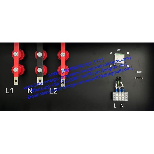
A split phase RLC load bank is a type of load bank that can simulate different types of loads by using resistors, inductors and capacitors in series. It can create pure resistive, pure inductive, pure capacitive or combined loads with leading or lagging power factor https://www.junxypowersolutions.com/resistive-capacitive-inductive-ac-load-bank. A split phase RLC load bank can also output two voltages that are 180 degrees out of phase with each other by using a center-tapped transformer. This allows it to test single-phase or three-phase power sources with different voltages, currents, power factors and harmonics. A split phase RLC load bank can also be used for inverter anti-islanding test, which is a safety feature that prevents an inverter from feeding power to the grid when the grid is down. https://www.junxypowersolutions.com/resistive-capacitive-inductive-ac-load-bank
The load bank is designed for the AC120V & AC240V 2phase 3wires split phase inverter load test. Include the pure resistive, pure inductive and pure capacitive loading or combination loading. Power factor adjustable. 2 control modes: local panel by push buttons & PC software remote control.

| Technical Specifications | ||
|---|---|---|
| Model | JUNXY-AC120V&240V-20KW-RLC Split Phase AC Load Bank | |
| Load Element | Stainless steel resistor, inductor & capacitor | |
| Load Voltage | Split-Phase: AC240V 2phase 3wires(L1/N/L2) AC120V(L1-N), AC120V(L2-N), AC240V(L1-L2) NOTE: Over voltage loading is PROHIBITED | |
| Load Frequency | 60Hz | |
| Total Load Power | R=20.2KW @AC240V 2P3W, (10.1KVar per phase), L=20.2KVar @AC240V 2P3W, (10.1KVar per phase), C=20.2KVar @AC240V 2P3W, (10.1KVar per phase) | |
| Resistive Load Steps | L1-N@AC120V: 0.01KW, 0.02KW*2, 0.05KW, 0.1KW, 0.2KW*2, 0.5KW, 1KW, 2KW*2, 4KW (10W-10.1KW adjustable) L2-N@AC120V: 0.01KW, 0.02KW*2, 0.05KW, 0.1KW, 0.2KW*2, 0.5KW, 1KW, 2KW*2, 4KW (10W-10.1KW adjustable) L1-L2@AC240V: 0.02KW, 0.04KW*2, 0.1KW, 0.2KW, 0.4KW*2, 1KW, 2KW, 4KW*2, 8KW (20W-20.2KW adjustable) | |
| Inductive Load Steps | L1-N@AC120V: 0.01KVar, 0.02KVar*2, 0.05KVar, 0.1KVar, 0.2KVar*2, 0.5KVar, 1KVar, 2KVar*2, 4KVar (10Var-10.1KVar adjustable) L2-N@AC120V: 0.01KVar, 0.02KVar*2, 0.05KVar, 0.1KVar, 0.2KVar*2, 0.5KVar, 1KVar, 2KVar*2, 4KVar (10Var-10.1KVar adjustable) L1-L2@AC240V: 0.02KVar, 0.04KVar*2, 0.1KVar, 0.2KVar, 0.4KVar*2, 1KVar, 2KVar, 4KVar*2, 8KVar (20Var-20.2KVar adjustable) | |
| Capacitive Load Steps | L1-N@AC120V: 0.01KVar, 0.02KVar*2, 0.05KVar, 0.1KVar, 0.2KVar*2, 0.5KVar, 1KVar, 2KVar*2, 4KVar (10Var-10.1KVar adjustable) L2-N@AC120V: 0.01KVar, 0.02KVar*2, 0.05KVar, 0.1KVar, 0.2KVar*2, 0.5KVar, 1KVar, 2KVar*2, 4KVar (10Var-10.1KVar adjustable) L1-L2@AC240V: 0.02KVar, 0.04KVar*2, 0.1KVar, 0.2KVar, 0.4KVar*2, 1KVar, 2KVar, 4KVar*2, 8KVar (20Var-20.2KVar adjustable) | |
| Power Factor | Leading and lagging power factor 0-1.0 adjustable | |
| Load Accuracy | R/C: ±5%, L: ±10%, | |
| Digital Meter | Voltage, Current, Power, Frequency, Power Factor and etc. | |
| Power Supply | AC120V 60Hz, single phase | |
| Control Mode | 1. Manual control by push button 2. Remote control by PC software | |
| Wire Connections | Copper bus bar for wire connections | |
| Insulation Class | F | |
| Protection Level | IP20(indoor use) | |
| Fan Noise | 75dB | |
| Cooling Mode | Force-air vertical cooling | |
| Work Mode | Continuous work |