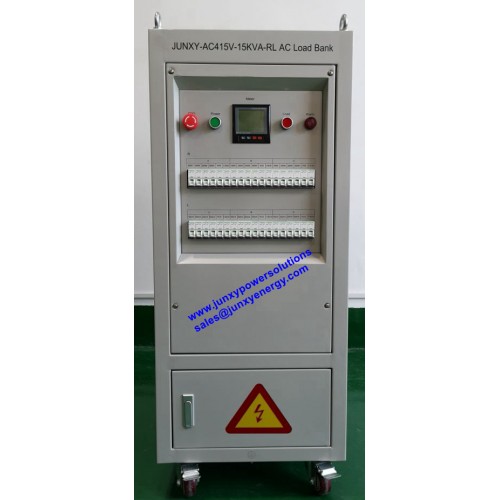
JUNXY resistive & inductive AC load banks are used to simulate the motor loads or other electromagnetic devices working at their rated power factor. Many backup generators and turbines are rated at 0.7, 0.8 or 0.85 power factor and need to be commissioned at nameplate capacity using a combination of resistive and reactive load to fully qualify their operating capability. Using a resistive & reactive load bank enables comprehensive testing from a single unit.
JUNXY has an extensive range of resistive & reactive load banks to simulate these types of loads on a power source and the transformers, relays, and switches which will distribute the power throughout your facility.
| JUNXY resistive & inductive load banks-RL | |||||||||||||
|---|---|---|---|---|---|---|---|---|---|---|---|---|---|
| Model | AC230V-6kW-RL | AC480V-30kW-RL | AC480V-60kW-RL | AC480V-100kW-RL | AC480V-200kW-RL | AC480V-500kW-RL | |||||||
| Capacity | Resistive load: 6kW Inductive load: 4.5kVAR |
Resistive load:30kW Inductive load: 22.5kVAR |
Resistive load: 60kW Inductive load: 45kVAR |
Resistive load: 100kW Inductive load: 75kVAR |
Resistive load: 200kW Inductive load: 150kVAR |
Resistive load: 500kW Inductive load: 375kVA |
|||||||
| Customized solutions could be available upon request. | |||||||||||||
| Rated Voltage |
Single Phase, AC230V |
Three Phase AC480V, or units can be specified by customer |
|||||||||||
| Customized solutions could be available upon request. | |||||||||||||
| Rated current at 480VAC |
Resistive amperes per phase: 26A Reactive amperes per phase: 20A |
Resistive amperes per phase: 36A Reactive amperes per phase: 27A |
Resistive amperes per phase: 72A Reactive amperes per phase: 54A |
Resistive amperes per phase: 120A Reactive amperes per phase: 90A |
Resistive amperes per phase: 240A Reactive amperes per phase: 180A |
Resistive amperes per phase: 601A Reactive amperes per phase: 451A |
|||||||
| PF | PF=0.8 | ||||||||||||
| Minimum Load Step | 100W, 100VAR | 100W, 100VAR | 100W, 100VAR | 1kW, 1kVAR | 1kW, 1kVAR | 1kW, 1kVAR | |||||||
| Customized solutions could be available upon request. | |||||||||||||
| Display | Voltage, Current, Frequency, Power and PF displayed by digital meter | ||||||||||||
| Protection | Overheating alarm, Short circuit protection, Overheating protection, Fan overloading protection, Emergency stop button. All protections can be configured optionally |
||||||||||||
| Control Mode | Manual control by MCBs or push buttons | ||||||||||||
| Air Flow | Horizontal, Force-air cooling | ||||||||||||
| Dimension | 51*50*110(cm) | 90*90*160(cm) | 90*90*200(cm) | 120*120*200(cm) | 90*90*200(cm) | 120*120*200(cm) | |||||||
| Options | Handle panel or PC remote control selectable | ||||||||||||